Showing 162 results

Archival description
Residential buildings
Print preview View:

29 results with digital objects Show results with digital objects

Case study: Housing for the elderly, The Mount, St. John's Road, Woking, Surrey

Material related to the submission of a case study as part of post Year 5, RIBA Part 3. It consists the details of the construction stage of two stories blocks of bedsits and large block of 1 bedroom flats for elderly people, Surrey. This case study submitted by the architect when he was joined Hutchison Locke and Monk's offices in Richmond, October 1981. As described by the architect, the submission includes his observations during his visits to the site, recording the official site meetings, and sub-contractors meetings. The submission is in the form of comb binding document of typewritten style with some maps, photos from the site, minutes from meetings, and progress reports.

Platt, Christopher

Housing design/Project 1: Third floor plan, and Fourth floor plan

Architectural drawing on tracing paper related to the design of Project 1 including the third floor plan and fourth floor plan in scale 1:100. It shows the design of the third floor plan indicating the functional spaces for three flats. Each flat has: 2 bedrooms, kitchen, living & dining room, 2 bathrooms, storage, and balcony. The areas of these flats are smaller than the second floor. It also shows the design of the fourth floor plan which has three flats with the same number of spaces but with areas that are smaller than the third floor flats.

Platt, Christopher

Housing design/Project 1: North elevation, and Long section

Architectural drawings on tracing paper related to the design of Project 1 including north elevation in scale 1:200, and long section in scale 1:100. The north elevation shows the design of the main building mass, height, and external materials. The long section shows the floors' main structural elements: floors, slabs, and staircase. These drawings have no indication of the types of materials used.

Platt, Christopher

Housing design/Project 1: South elevation, and Isometric

Architectural drawing on tracing paper related to the design of Project 1 including south elevation in scale 1:200, and an isometric in scale 1:100. the design of the south elevation presents the main building mass, height, and external materials. These drawings have no indication of the types of materials used, however it gives the outline of the main design concept. It also shows how the building fits with the surroundings landscape. The isometric shows the building in its three dimensional view representing the final shape of the building.

Platt, Christopher

Material related to Housing design/Project 2: Block no.2: corner pub, ground floor (lower level)

Architectural drawing on tracing paper related to Housing design project 2 representing block 2 corner pub ground floor plan (lower level) in scale 1:200. The block's layout takes a triangle shape. The pub fills one of the triangle corner with different window styles. Flats are located along the block's outer sides surrounding an inner courtyard, with flats indicated: 3P, 2P, 1P, and 5P. There are two main entrances to the courtyard which consists of cars parking, closed gardens for the ground flats, and children's play area.

Platt, Christopher

Material related to Housing design/Project 2: Block no.2: corner pub, interior south elevation & cross section

Architectural drawing on tracing paper related to Housing design/project 2 represents block 2 corner pub interior south elevation and cross section in scale 1:200. The elevation show the building façade elements from the inner courtyard. This drawing gives a clear image of the site typology that affected the continuity of the block's floors plan levels and reflects that on the skyline of the building across the block. There is no indication of the finishing materials nor the height of the buildings.

Platt, Christopher

Material related to Housing design/Project 2: Block no.2: Raeberry St., Internal court & Cross section

Architectural drawing on tracing paper related to Housing design/project 2 represents block 2 'corner pub' elevation facing Raeberry St., internal court elevation, and cross section in scale 1:200. The cross section shows the differences in the site's levels and how the ground topography affects the design of the main entrances to the courtyard. This section shows the ratio of the building height to the opened space span. The architect used colour on part of the elevation to give an idea of the final look of the building facades.

Platt, Christopher

Material related to Housing design/Project 2: Block 4P and P2: 3rd/4th plan, and section

Architectural details drawing on tracing paper related to Housing design/project 2 represents Block 4P and its connection with P2 through the third and forth floor plans all in scale 1:50. The third floor has four symmetrical flats. The main entrance to Flat 4P leads to two bedrooms and a staircase to the upper floor which consists an open living room/dining room with an open kitchen and two bathrooms. The cross section shows the main structural elements of the building construction system. On the fourth plan the roof of flat 4P appears with its skylight windows.

Platt, Christopher

Material related to Housing design/Project 2: Block 4P: Street elevation south, and Court elevation north

Architectural details drawing on tracing paper related to Housing design/project 2 represents Block 4P and 2P elevations in scale 1:50. Both the street and the court elevations are in coloured rendering to identify finishing materials used. The facades are designed to reflect the floor plans and their interior spaces. The elevations are in the same traditional style of most residential buildings in the city.

Platt, Christopher

Housing design/Project 1: Fifth floor plan, and Sixth floor plan

Architectural drawing on tracing paper related to the design of Project 1 including the fifth floor plan and sixth floor plan in scale 1:100, showing the design of the penthouse flat, indicating its functional spaces divided into two levels. The fifth floor shows the first level of the penthouse including one bedroom with other facilities. The second level based on the the sixth floor including one bedroom with facilities but is larger in area than the first level on the floor below. The penthouse is located at the central point of the floors' plans and raised in the building height leaving the right and left wings of the building lower than the centre.

Platt, Christopher

Material related to Housing design/Project 2: Block no.2: corner pub, ground floor (upper level)

Architectural drawing on tracing paper related to Housing design/project 2 represents block 2: corner pub and its ground floor plan (upper level) in scale 1:200. This block layout takes a triangle shape. The pub fills one of the triangle corner with several semi-circular façade windows. Flats are located along the block's outer sides surrounding an inner courtyard. The flats are indicated: 4P, 2P, 3P, and GP. There is just one main entrance from the main street to the inner courtyard/upper level, which consists of a picnic area and children's playground.

Platt, Christopher

Housing design/Project 1: East elevation, and Cross section

Architectural drawing on tracing paper related to the design of Project 1 including east elevation in scale 1:200, and cross section in scale 1:100. It shows the design of the east elevation, its main building mass, height, and external materials. The cross section shows the floors' main structural elements: floors, slabs, and staircase. These drawings have no indication of the types of materials used nor height dimensions, however it gives the outline of the main design concept. It also represents how the building fits with the surrounding landscape.

Platt, Christopher

Material related to Housing design/Project 2: Site plan

Architectural drawing on tracing paper related to the housing design/project 2 showing the site plan in scale 1:1250, representing its main blocks with the north sign. The new blocks for the housing design project have been coded with numbers and given titles, as below:

  • 1: students' hostel;
  • 2: corner pub;
  • 3: nursery school;
  • 4: tenement with G-floor shops;
  • 5: public building/shops;
  • 6: flats;
  • 7: new housing;
  • 8: terraced housing;
  • 9: public building/shops.

The architect used shading to give an idea of the height of each new building within the site plan.

Platt, Christopher

Material related to Housing design/Project 2: Block no.2: corner pub (1st, 2nd & 3rd floors)

Architectural drawing on tracing paper related to Housing design project 2 representing block 2 corner pub, a typical floor plan for each of the first, second, and third floors in scale 1:200. The block's layout takes a triangle shape. It shows the different levels on one side of the block affected by the site's topography which results in a discontinuity of the same floor level for the three triangle sides. Flats are indicated: 5P, 3P, 2P, and GP. Each flat shows the main functional spaces, in addition to the main vertical circulation of the other flats within the blocks.

Platt, Christopher

Material related to Housing design/Project 2: Block 4P: Ground plan, 1st/2nd plan, and section

Architectural drawing on tracing paper related to Housing design/project 2 represents Block 4P flats and their drawing details including ground, first, and second floor plans all in scale 1:50. Each floor has two symmetrical flats. Each flat consists of two bedrooms, living room and dining room with an open kitchen, and two bathrooms. A central main entrance connects the main street with the back yard including the services shafts as well as showing the design of the flooring tiles. The cross section shows the floor height and the main staircase. The architect used the ceiling of the main entrance to add some decoration using some hanging plants to give the central volume a sense of environmental quality effect. The section also shows the main structural elements but without any indications of material types.

Platt, Christopher

Material related to Housing/Project 2: Site plan-isometric

Architectural drawing on tracing paper related to housing design/project 2 showing the site plan in scale 1:1250, representing the main housing blocks in an isometric birds-eye view. This site plan gives an idea of the built spaces in relation to the open spaces. However, there is no indication of street names or existing buildings.

Platt, Christopher

Material related to Housing design/Project 2: Block no.2: corner pub, fourth floor

Architectural drawing on tracing paper related to Housing design/project 2 representing block 2 corner pub fourth floor plan in scale 1:200. It shows the maisonette plan of flat 7P and its main functional spaces and how it relates to its upper level. The plan also includes other flats for the same block with their main vertical circulation.

Platt, Christopher

Housing design/Project 1: Site plan

Architectural drawing on tracing paper related to the design of the Housing/Project 1 including the site plan in scale 1:200. It shows how the new building fits within the urban site of the selected location. This drawing has no indication to the names of the streets nor the existing buildings, therefore the location is unknown. North sign has been added to the drawing. The new building has been highlighted with hatched lines in grey colour.

Platt, Christopher

Housing design/Project 1: First floor plan, and Second floor plan

Architectural drawing on tracing paper related to the design of Project 1 including the first floor plan and second floor plan in scale 1:100. It shows the design of the first plan indicating the functional spaces for three flats. Each flat has: 2 bedrooms, kitchen, living & dining room, 2 bathrooms, storage, and balcony. It also shows the design of the second floor plan which has three flats with the same number of spaces but with areas that are smaller than the first floor flats.

Platt, Christopher

Housing design/Project 1: Ground floor plan, and Basement floor plan

Architectural drawing on tracing paper related to the design of Project 1 including ground floor plan and basement floor plan in scale 1:100. It shows the design of the ground plan indicating the functional spaces of the caretaker's flat and other spaces for communal purposes. It also includes the design of the landscape within the site, the outdoor spaces, trees, outdoor patio shades, and steps.
It also shows the design of basement floor plan indicates parking and plant presenting the layout of the car parking and its main entrance, staircase and lift, but without any indication to the design details.

Platt, Christopher

Existing boathouse

Architectural drawings of the existing boathouse showing the floor plans, sections, and elevations in scale 1:100. The drawings are all Rotring ink pen on tracing paper. The drawings are in their real measurement, however, there is no mention of the names of the spaces or the materials used on elevations and sections. The aim of this material is to study the existing boathouse and get an idea about the design of such a building.

Platt, Christopher

A boathouse in the manner of Charles Moore: Conversion of the existing boathouse; Elevations and sections

Architectural drawings of the conversion of an existing boathouse showing the four elevations (west, east, north, and south), and sections (section AA, section BB, and section CC), all in scale 1:100. The drawings are all Rotring ink pen on a tracing paper. The drawings show the final work of the refurbishment that the architect planned to develop the existing building. These drawings showing the interior design of the indoor space and the new elements added, however, there is no mention of the types of materials used.

Platt, Christopher

A boathouse in the manner of Charles Moore: Conversion of the existing boathouse; Plans and isometric

Architectural drawings of the conversion of an existing boathouse showing the floor plans, and an interior isometric scale 1:100. The drawings are all Rotring ink pen on tracing paper. The drawings show the final work of the refurbishment that the architect plans to develop the existing building. In its plan stage, the architect redesigned the interior spaces and added some extensions that would change the outdoor look. The interior isometric shows the new redesign in 3D.

Platt, Christopher

A boathouse in the manner of Charles Moore: Conversion of the existing boathouse; site plan

An architectural drawing on tracing paper showing the site plan and site section scale 1:500 of the conversion of an existing boathouse. The site for this project is unidentified.

Platt, Christopher

A boathouse in the manner of Charles Moore: Conversion of the existing boathouse; Plans, elevations and sections

Architectural drawings of the conversion of an existing boathouse including two elevations (west facing the river, and south), and sections (section AA, section BB, and section CC), all in scale 1:100. The drawings are all Rotring black ink pen on tracing paper, with several coloured areas. The drawings show the design in the initial stage representing the refurbishment that the architect planned to develop the existing building focusing on the indoor space and the new elements added.

Platt, Christopher

The work of Richard Meier: A family house in the style of Richard Meier, elevations and sections

Material related to studying a family house designed by Richard Meier including architectural drawings on greaseproof paper using Rotring drawing ink pens. The architectural drawings consist of: west elevation, east elevation, north elevation, and south elevation, as well as section AA, and section BB, all in scale 1:100. These drawings show the functional spaces, and horizontal and vertical circulations. The aim is to address the design style that Richard Meier adopted which is mainly focused on the clear geometry both for the solid walls and shape of window openings.

Platt, Christopher

The work of Richard Meier: Private buildings

Material related to studying the work of Richard Meier including architectural drawings of some of his private projects as well as written information about his career and firms he worked with. All on greaseproof paper using Rotring drawing ink pens. In the written information, Platt studied Richard Meier's career related to the firms he worked with, such as:

  • American monumental tradition: Mies Van Der Rohe, Philip Johnson, Eero Saarinen, and Skidmore and their relations to Le Corbusier
  • Walter Gropius and other architects from the post war generation
  • The New York Five: Peter Eisenman, Michael Graves, John Hejduk, and Gwathmey & Siegel.

The aim of this study is to address the priorities taken from Le Corbusier's private buildings: clarity & expression of structure, vertical circulation as a major design element, use of double height living spaces, and natural influence.
Then, the architect moved to study some examples from Richard Meier's houses, like: Smith house, Saltzman house, and Shamberg house. The architect aimed to address the priorities used in all houses, for example: definition of public and private spaces, open space revealed by entry through closed space, and many other issues.

Platt, Christopher

The work of Richard Meier: A family house in the style of Richard Meier, floor plans

Material related to studying a family house designed by Richard Meier including architectural drawings on greaseproof paper using Rotring drawing ink pens. The architectural drawings consist of: ground floor plan, first floor plan, second floor plan, and roof plan, all in scale 1:100. These drawings show the functional spaces and horizontal and vertical circulations.

Platt, Christopher

The work of Richard Meier: A family house in the style of Richard Meier, Detailed section

Material related to studying a family house designed by Richard Meier including architectural drawings on tracing paper using Rotring drawing ink pens. The architectural drawings consist of: cross section the building scale 1:20, and cross section and plan of curtain wall scale 1:5. The aim of such detailed drawings is to study the construction methods, main structure elements (steel columns), sub-structure elements using timber studs, and finishing materials.

Platt, Christopher

The work of Richard Meier: A family house in the style of Richard Meier, Details

Material related to studying a family house designed by Richard Meier including architectural detail drawings on tracing paper using Rotring drawing ink pens. The architectural drawings consist of: section & plan through typical opening scale 1:5, section of column and beam (1st & 2nd floors) scale 1:10, section through glazed vault, section through walkway floor scale 1:5, section through cantilevered roof floor scale 1:10, section & plan through steel column scale 1:5. The aim of such detailed drawings is to study the construction methods that shaped the form of the house.

Platt, Christopher

The work of Richard Meier: A family house in the style of Richard Meier, Structural arrangement

Material related to studying a family house designed by Richard Meier including architectural detail drawings on tracing paper using Rotring drawing ink pens. The architectural drawings consist of: foundation plan, floor plans scale 1:200, elevations (west, east, south, and north) scale 1:200, and cut-away isometric view scale 1:100. The aim of such detailed drawings is to study the structural arrangement, from foundation to roof, the structural grid of the steel columns and timber beams and how the mechanical services aligned within the structural system.

Platt, Christopher

The work of Richard Meier: A family house in the style of Richard Meier

Material related to studying a family house designed by Richard Meier including architectural drawings on greaseproof paper using Rotring drawing ink pens. The architectural drawings consist of: site plane scale 1:500, axonometric view scale 1:200, and drawings related to the building analysis of the site, programme, structure, circulation, enclosure, and entrance, all in scale 1:500.

Platt, Christopher

Living with the river

Material related to studying examples of living with the river such as a lake dwellings from Japan, Kohama 6000 B.C describing the strategic reasons behind the design of such community dwellings. All the drawings are freehand sketches on tracing paper showing the site plans from an iron age village addressing the way to reach these dwellings from mainland by canoes. Another example of living with the river is the pile dwellings or the Saigon Shacks where they built on piles raised above the water because there is not enough room on the mainland for more houses.

Platt, Christopher

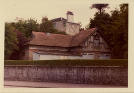
The coach house, 47 Eldon Street, Greenock: photograph

A photograph taken by the architect showing the front view of the coach house from the main road (Eldon Street), showing the Health Board Headquarters building situated on top of the hill above the coach house.

Platt, Christopher

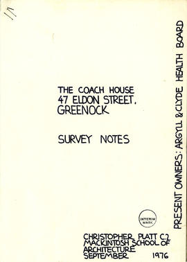
The coach house, 47 Eldon Street, Greenock: Survey notes (page1)

12 cartridge paper sheets including free hand sketches of the coach house ground floor plan, upper floor plan, section CC, section BB, section AA, N.W elevation, N.E elevation, S.W elevation, S.E elevation, and several architectural details including gate, window, and cast iron fireplace. Although these drawings are all free hand sketches, they also include details of the entire building's dimensions and materials used indoors and outdoors.

Platt, Christopher

The coach house, 47 Eldon Street, Greenock: photograph

A photograph taken by the architect showing the front view of the coach house from the main road (Eldon Street). The coach house's layout is on a diagonal position giving the front elevation and the other side elevation a good angle to face the main road traffic.

Platt, Christopher

The coach house, 47 Eldon Street, Greenock: upper floor plan

A tracing paper drawing showing the architectural details of the upper floor plan in scale 1:50, showing the functional spaces including: coach house, stables, coachman's living room, coachman's bedroom, bathroom, sorting/store room and hayloft.

Platt, Christopher

The coach house, 47 Eldon Street, Greenock: N.W. & S.W. elevations

A tracing paper drawing showing the architectural details of the north-west elevation and south-west elevation in scale 1:50, showing the external views of the building with finishing materials. The north west elevation gives an idea of the original outdoor building view before adding the corrugated sheets as mentioned on the ground floor plan. Black ink is used to render the building lines and window shades, while Zip-a-Tone has been used to render shadows created by the different levels of the external building's parts.

Platt, Christopher

Results 1 to 50 of 162