Proposed plan and axonometric view 3
- DC 121/1/5/11
- Item
- Sep 1974-May 1975
Tracing paper showing the final proposed plan of the study bedroom and its axonometric view that meets all the required design criteria.
Platt, Christopher
3 results with digital objects Show results with digital objects
Proposed plan and axonometric view 3
Tracing paper showing the final proposed plan of the study bedroom and its axonometric view that meets all the required design criteria.
Platt, Christopher
Free hand sketch showing some architectural details of Royal Exchange Square and describing the public circulation as:
Platt, Christopher
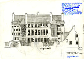
Scotland Street School, North Elevation
Free hand sketch showing the north elevation of Scotland Street School including some architectural descriptions, for example, "scale has been a major design factor in this building for children, windows diminish in height as they rise from the floor, and the wall has been set back to lessen the effect of three stories. Not every room in a building has the same height, each houses a different function and should be designed with that function in mind".
Platt, Christopher
Scrapbook featuring material collected throughout Christopher Platt's study at The Mackintosh School of Architecture including different articles, photos, and subjects from different magazines, like: The New York Times Magazine, Observer Magazine, The Sunday Times, Telegraph Sunday Magazine, and other resources. It also includes some free-hand sketches.
Platt, Christopher
Sheet 1, The Glasgow School of Art, North Elevation
The Glasgow School of Art north elevation as it drawn as it was in 1910, without any written information about the architect, the history of the building.
Platt, Christopher
Sheet 2, The Glasgow School of Art, South Elevation
The Glasgow School of Art south elevation drawn as it was in 1910, without any written information about the architect, the history of the building.
Platt, Christopher
Sheet 3, The Glasgow School of Art, West and East Elevations
West elevation: drawn from a contract drawing of 1907 re-design of the original 1896 and altered by architect amending doorway, architrave, and corbels.
East elevation: drawing shows the building as built originally planned except for slight modifications.
Platt, Christopher
Sheet 4, The Glasgow School of Art, Floor Plans
Presentation sheet including copies of floor plan drawings and a photo of the east staircase at first-floor level. No references included.
Platt, Christopher
Sheet 5, The Glasgow School of Art, Wrought Iron Features
The presentation sheet includes photos of some wrought iron features with descriptions about the functional and aesthetics values of using such features as they were attached to the windows, above the main entrance, and balcony railings. Photos' references are unknown.
Platt, Christopher
Sheet 6, The Glasgow School of Art, Wrought Iron Features
The presentation sheet includes photos of some main features of the library such: pendant cluster of pierced metal lampshades, the construction of the coffered ceiling pillars and balusters. Photos' references are unknown.
Platt, Christopher
Sketchbook containing free-hand sketches created throughout Christopher Platt's study at The Mackintosh School of Architecture covering different buildings, locations, and landscape. These drawings show architectural details from indoor and outdoor views as self-observation undertaken by the student.
Platt, Christopher
Free hand sketches of space requirements showing the furniture dimensions and the space around them to meet the movement and functional standard.
Platt, Christopher
Sports council headquarters: Conceptional diagrams
Free hand sketches on tracing paper showing the sports council headquarters building in its conceptual stage. The drawings are in scale 1:200 and show diagrams of:
Platt, Christopher
Sports council headquarters: First floor plan
Architectural drawing of the first floor plan on tracing paper in scale of 1:100 showing the design of a sports council headquarters building in its final design stage. The first floor consists of: sport council H.Q. administration, the vertical circulation, the void of the sports hall, and other services.
Platt, Christopher
Sports council headquarters: Fourth floor and basement plans
Architectural drawing of the fourth floor and basement plans on tracing paper in scale 1:100 showing the design of a sports council headquarters building in its final design stage. The fourth floor consists of: caretakers flat, terrace, vertical circulation, plant room, and other services. The basement plan consists of: printing section, press offices, vertical circulation, plant room, and other services.
Platt, Christopher
Sports council headquarters: Ground floor plan
Architectural drawing of the ground floor plan on tracing paper in scale 1:100 with free hand sketches in scale 1:200, showing the design of a sports council headquarters building in its final design stage. The ground floor consists of: sporting exhibition audio and visual displays, cafeteria, main entrance with vertical circulation, sports hall, and other services.
Platt, Christopher
Sports council headquarters: Large rolled sheet
Architectural drawing on a large rolled tracing paper including site plan, cross section, axonometric, and hinged elevational projection. The site plan is 1:500 showing the location of the new building and its position on the corner of the site. The cross section is in scale 1:100 showing the main functions for each floor and their connections to the outdoors through opened balconies. It also shows the main structural system. There are some spaces with double volume and looking down to the floor below. This large rolled sheet also includes a hinged elevational projection in scale 1:100, which is drawn as a panorama presenting the new building elevation and its position in the point of the existing buildings on Clyde Street and Bridgegate Street. It shows the contrast between the design traditional style of the existing building with their rich architectural details against the modern style design of the new building.
Platt, Christopher
Sports council headquarters: Long section
Architectural drawing on tracing paper of a long section in scale 1:100 showing the design of a sports council headquarters building in its final design stage. This drawing seems to be the first draft of the long section (ref: DC 121/5/3/7). It isn't a copy, but maybe the first attempt from the architect to study the design of the building in its cross vertical section.
Platt, Christopher
Architectural drawing on tracing paper of long section in scale 1:100 and two other details section in scale 1:20 showing the design of a sports council headquarters building in its final design stage. The long section shows the structural system of the new building and its connection to the existing sport hall. The floor heights with their main construction elements show the names of each functional spaces. The two other sections are more in detail indicating the materials used for floor slabs, ceilings and walls.
Platt, Christopher
Sports council headquarters: Second and third floors plans
Architectural drawing of the second and third floors plans on tracing paper in scale 1:100 showing the design of a sports council headquarters building in its final design stage. The second floor consists of: lounge bar and a terrace, open plan space for facilities planning sports development, vertical circulation, and other services. In addition, the third floor plan consists of: offices, covering bodies' accommodation, vertical circulation, and other services.
Platt, Christopher
Sports council headquarters: Site analysis
Free hand sketch on tracing paper including the site analysis of sports council headquarters. The drawing is in scale 1:500 and shows the location for the building which is at Glasgow City Centre near Victoria Bridge, facing the Clyde River bank. This drawing analyses the mains roads and streets surroundings the site, pedestrian traffic to and from Glasgow Green focusing on the corner of the site to make used of the nice views from site, and the relationship of the building to the existing facades and its connection with the river view. It also indicates the North sign and addresses the prevailing winds from south west for the best environmental natural elements.
Platt, Christopher
Strathclyde University's new graduation hall: Elevations, and section
Architectural drawing on tracing paper consisting of the elevation of the new hall from the Cathedral Square façade, and from the west elevation, all in scale 1:200. The Cathedral square elevation shows the new hall from Castle Street presenting the external view of the new hall with Barony Hall and how the new architectural style differs from the traditional building style. There are no indications about the material types used within the new design. The main idea of the new hall is in its building height which did not dominant the skyline of the campus building and Barony Hall which is still standing to be the focal point of the site. The cross section shows the main hall and its functional spaces in its vertical dimension with the structural elements of the interior columns and the central skylight.
Platt, Christopher
Strathclyde University's new graduation hall: Ground floor plan
Architectural drawing on a tracing paper showing the ground floor plan, scale 1:200, of a new graduation hall at the University of Strathclyde. The ground plan design shows the main functional spaces for the new hall: the main hall, professional entrance, the building entrance, kit staff, stage staff, chair staff, and other services. For the exterior spaces, the plan shows the external spaces attached with the new hall, like: permanent exhibition, lecture theatre, temporary exhibition, bar, reception, and university bookshop. It also shows the design of the landscape.
Platt, Christopher
Strathclyde University's new graduation hall: Site plan
Architectural drawing on tracing paper showing the site plan of a new graduation hall at the University of Strathclyde in scale 1:1000. The site plan has no street names, however, it is easy to identify the location of the new graduation hall as the site plan shows how the new hall is connected with Barony Hall. The North sign is present on this material. It also shows the design of the new landscape that goes behind the site boundary to make the new hall integrated within the main University campus.
Platt, Christopher
Strathclyde University's new graduation hall: Upper floor plan, and basement
Architectural drawing on tracing paper consisting of the upper floor plan and the basement floor plan, scale 1:200, of a new graduation hall at the University of Strathclyde. The upper plan design shows: the upper lounge looking down to the main hall with its double volume, the organ's position, the cleaner's store, vertical circulation, and other services. It also shows the upper plan of the external lecture theatre which consists of the upper display space and the project's position. The main structural system is based on cylinder columns supporting the roof, while the basement floor plan includes the plant room, exhibition storage chamber and other services. It also shows the connection between the hall basement and the cooling fountain.
Platt, Christopher
A free hand drawings consisting of the longitudinal section and plan.
Platt, Christopher
The coach house, 47 Eldon Street, Greenock: a copy of S.E & N.E elevations
A copy of south-east & north-east elevations showing the architectural details that the architect did for his summer project, second year.
Platt, Christopher
The coach house, 47 Eldon Street, Greenock: a copy of sectional perspective AA
A copy of the sectional perspective showing the architectural details that the architect did for his summer project, second year.
Platt, Christopher
The coach house, 47 Eldon Street, Greenock: a copy of sections BB & CC
A copy of sections BB and CC showing the architectural details that the architect did for his summer project, second year. The original title stated it as sections AA & BB, but the drawings show sections BB and CC.
Platt, Christopher
The coach house, 47 Eldon Street, Greenock: a copy of the ground floor plan
A copy of the ground floor plan showing the architectural details that the architect did for his summer project, second year.
Platt, Christopher
The coach house, 47 Eldon Street, Greenock: a copy of the upper floor plan
A copy of the upper floor plan showing the architectural details that the architect did for his summer project, second year.
Platt, Christopher
The coach house, 47 Eldon Street, Greenock: ground floor plan
A tracing paper drawing showing the architectural details of the ground floor plan in scale 1:50, showing the functional spaces including: coach house, stables, coachman's living room, and coachman's kitchen/dining room. A dotted line on the north west side shows the position where a line of corrugated sheets are added later.
Platt, Christopher
The coach house, 47 Eldon Street, Greenock: N.W. & S.W. elevations
A tracing paper drawing showing the architectural details of the north-west elevation and south-west elevation in scale 1:50, showing the external views of the building with finishing materials. The north west elevation gives an idea of the original outdoor building view before adding the corrugated sheets as mentioned on the ground floor plan. Black ink is used to render the building lines and window shades, while Zip-a-Tone has been used to render shadows created by the different levels of the external building's parts.
Platt, Christopher
The coach house, 47 Eldon Street, Greenock: S.E & N.E. elevations
A tracing paper drawing showing the architectural details of the south-east elevation and north-east elevations in scale 1:50, showing the external views of the building with finishing materials. Black ink is used to render the building lines and window shades, while Zip-a-Tone has been used to render shadows created by the different levels of the external building's parts.
Platt, Christopher
The coach house, 47 Eldon Street, Greenock: sectional perceptive AA
A tracing paper drawing showing the architectural details of the sectional perspective AA in scale 1:50, showing the interior spaces, finishing materials, structural system and construction methods. The left hand side of the building includes the stables and the hayloft showing the way the architect tries to address the connection between these functional spaces in a sectional perspective.
Platt, Christopher
The coach house, 47 Eldon Street, Greenock: sections BB & CC
A tracing paper drawing showing the architectural details of sections BB and CC in scale 1:50, showing the interior spaces, finishing materials, structural system and construction methods. Section BB shows the stables and the hayloft, and section CC shows the coach house and sorting/store room. The original title stated it as section AA & BB, but the drawings are of sections BB and CC.
Platt, Christopher
The coach house, 47 Eldon Street, Greenock: Survey notes
12 cartridge paper sheets including free hand sketches of the coach house ground floor plan, upper floor plan, section CC, section BB, section AA, N.W elevation, N.E elevation, S.W elevation, S.E elevation, and several architectural details including gate, window, and cast iron fireplace. Although these drawings are all free hand sketches, they also include details of the entire building's dimensions and materials used indoors and outdoors.
Platt, Christopher
The coach house, 47 Eldon Street, Greenock: upper floor plan
A tracing paper drawing showing the architectural details of the upper floor plan in scale 1:50, showing the functional spaces including: coach house, stables, coachman's living room, coachman's bedroom, bathroom, sorting/store room and hayloft.
Platt, Christopher
The first Unitarian Church Wisconsin (1950)
A drawing sheet consisting the external perspective view of the first Unitarian Church, Wisconsin, designed by Frank Lloyd Wright, with some written information describing the design of the church's roof as the peaked roof centrally depicts the function of the building and what goes on outside, that is hands clasped and raised in prayer.
Platt, Christopher
The first Unitarian Church Wisconsin (1950), Architect: Frank Lloyd Wright
A free hand drawing consisting the external perspective view of the first Unitarian Church, Wisconsin, designed by Frank Lloyd Wright.
Platt, Christopher
The first Unitarian Church, Wisconsin (1950)
A free hand drawing consisting the external perspective view of the first Unitarian Church, Wisconsin, designed by Frank Lloyd Wright describing the construction materials used on the exterior walls which gave the building an organic look.
Platt, Christopher
The Third Eye Centre: A copy of cross section
Copy of architectural drawing on a paper sheet showing a cross section of the Third Eye Centre, in scale 1:20. This material has no reference number, however, it seems that it comes from the same source of the item DC 121/5/4/3 (Boswell Mitchell & Johnston Architects & Planning Consultants in Feb 1975). It has been used by the architect to study the existing building before making the new changes.
Platt, Christopher
The Third Eye Centre: a copy of entrance screen front façade
Copy of architectural drawing on a paper sheet showing the design of the plan and elevation of entrance screen of the Third Eye Centre, in scale 1:20. This material made by Boswell Mitchell & Johnston Architects & Planning Consultants in Feb 1975, and has a reference number of 954/33. It has been used by the architect to study the existing building before making the new changes.
Platt, Christopher
The Third Eye Centre: A copy of the existing ground floor plan
Copy of architectural drawing on a paper sheet showing the main indoor spaces of the ground floor plan of the Third Eye Centre, in scale 1:20. This material has no reference number, however, it seems that it comes from the same source of the previous item (Boswell Mitchell & Johnston Architects & Planning Consultants in Feb 1975). It has been used by the architect to study the existing building before making the new changes.
Platt, Christopher
The Third Eye Centre: a small rolled sheet: front façade
Architectural drawing on a rolled greaseproof sheet to study the design of the front elevation of The Third Eye Centre, in scale 1:20. This drawing seems to be the first sketch as an attempt to present the main features of the façade. This sheet has been coloured from the back. The changes the architect made can be easily distinguished from the final submission shown within the large rolled sheet.
Platt, Christopher
The Third Eye Centre: Large rolled sheet
Architectural drawings on a large rolled greaseproof sheet to study the design of The Third Eye Centre in Glasgow as a side project which is directed by the tutor of the third full-time year course. This large rolled sheet consists of the architectural drawing of the building's ground floor plan in scale 1:100 showing its main functional spaces. It also consists of an enlarged part of the ground floor taken from the front side of the building with its upper floor plan, both in scale 1:50. This sheet also includes a sectional perspective in scale 1:20 taken from cash desk booking focal point looking towards its both sides to upstairs floor. This drawing consists of several human figures with humourous comments to give a sense of the real life of this social space. The rolled sheet also includes a coloured drawing of the front façade in scale 1:20, where the architect coloured this drawing from the back of the sheet.
Platt, Christopher
The Unitarian Church, "Frank Lloyd Wright - Architecture and space".
A drawing sheet consisting the external perspective view of the first Unitarian Church, Wisconsin, designed by Frank Lloyd Wright, with some written information from his book "Architecture and Space":
'In this story I am God', a quotation which Peter Blake inserted in the back cover of the book as he wrote: 'As the lawgiver of Modern Architecture,' Blake added, 'He had been compared to Moses'.
Platt, Christopher
The work of Richard Meier: A family house in the style of Richard Meier
Material related to studying a family house designed by Richard Meier including architectural drawings on greaseproof paper using Rotring drawing ink pens. The architectural drawings consist of: site plane scale 1:500, axonometric view scale 1:200, and drawings related to the building analysis of the site, programme, structure, circulation, enclosure, and entrance, all in scale 1:500.
Platt, Christopher
The work of Richard Meier: A family house in the style of Richard Meier, Detailed section
Material related to studying a family house designed by Richard Meier including architectural drawings on tracing paper using Rotring drawing ink pens. The architectural drawings consist of: cross section the building scale 1:20, and cross section and plan of curtain wall scale 1:5. The aim of such detailed drawings is to study the construction methods, main structure elements (steel columns), sub-structure elements using timber studs, and finishing materials.
Platt, Christopher
The work of Richard Meier: A family house in the style of Richard Meier, Detailed section
A second copy of the architectural drawings related to "A family house in the style of Richard Meier, Detailed section" sheet with some notes from the tutor.
Platt, Christopher